Dec 25, 2024
A pneumatic cylinder can look correctly sized on paper and still struggle on the machine. One common reason is that the cylinder was selected from bore size or nominal air pressure without checking how much force is actually required at the load.
Pneumatic air cylinder force calculation starts with a simple relationship between pressure and piston area. The useful part, however, is knowing which pressure and area to use, how push and pull force differ, and how much margin the application needs before choosing a standard cylinder bore.
This guide explains the calculation step by step and, more importantly, how to use the result when selecting a pneumatic cylinder for pushing, pulling, lifting, clamping, positioning, and other industrial motions.
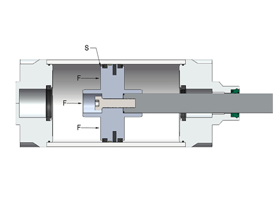
F = P × A
•F = theoretical cylinder force
•P = pressure available at the cylinder
•A = effective piston area
When pressure is expressed in N/mm² and area in mm², the result is directly obtained in newtons (N).
1 MPa = 1 N/mm²
So a working pressure of 0.6 MPa can be used as 0.6 N/mm² in the calculation. The formula is straightforward. Choosing the correct effective area requires a little more attention.
For the extension stroke of a conventional single-rod cylinder, compressed air acts on the full piston area:
A = πD² / 4
F(extension) = P × πD² / 4
where D is the cylinder bore diameter.
During retraction, the piston rod occupies part of the pressure area. The effective area is therefore smaller:
A = π(D² − d²) / 4
F(retraction) = P × π(D² − d²) / 4
where d is the piston rod diameter. This is why a single-rod double-acting cylinder produces less pulling force than pushing force at the same working pressure.
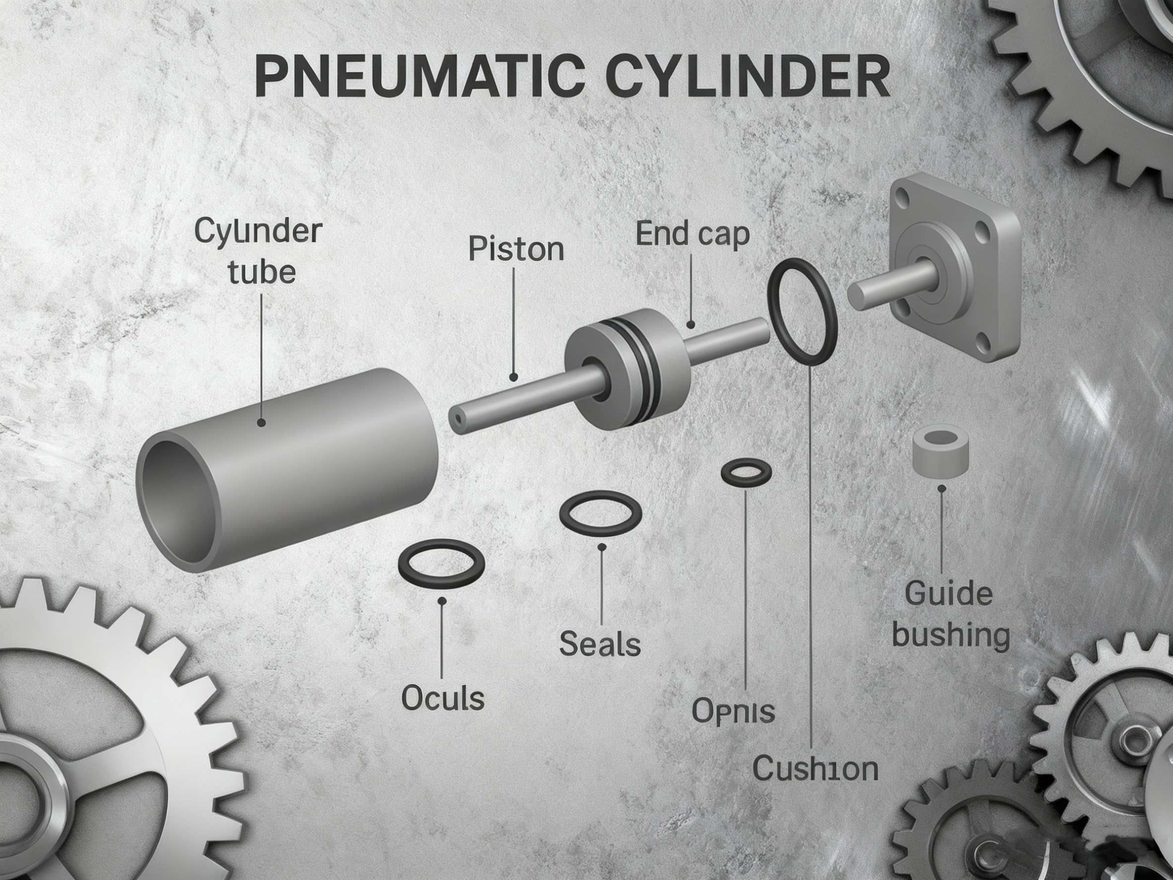
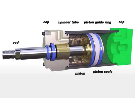
If the relationship between the piston, piston rod and cylinder tube is unfamiliar, our guide to the critical parts of a pneumatic cylinder explains these components and their functions in more detail.
This is one of the most important details in cylinder force calculation.
Suppose a plant air system is supplied at 0.7 MPa. It does not automatically mean that the cylinder has 0.7 MPa available while it is moving.
The circuit may be regulated to a lower pressure, and additional pressure losses can occur through the air preparation unit, valve, tubing, fittings, silencers and other restrictions. The pressure available during motion can therefore be lower than the nominal compressor or main-line pressure.
For initial sizing, use a realistic minimum operating pressure at the cylinder rather than the highest pressure the system can reach.
This distinction becomes more important when the required force is close to the cylinder's available force. A design that works with an optimistic pressure assumption may have very little margin when supply pressure changes or the machine operates at full production speed.
Consider a pneumatic cylinder with a 50 mm bore and a working pressure of 0.6 MPa.
A = π × 50² / 4 ≈ 1,963 mm²
F = 0.6 × 1,963 ≈ 1,178 N
This is approximately 120 kgf. So, at 0.6 MPa, a 50 mm bore cylinder produces approximately 1.18 kN of theoretical extension force.
But this does not mean that the cylinder should automatically be selected for a 120 kg working load. The calculated value is theoretical force at the piston. A real machine still has to overcome seal friction, mechanism friction, acceleration, pressure variation and other resistance. Load direction and machine geometry can also change the force required from the cylinder.
For an illustrative sizing example, if the design uses an 80% load ratio:
1,178 × 0.8 ≈ 942 N (about 96 kgf)
The 80% value here is an example used to demonstrate the sizing process, not a universal pneumatic-cylinder correction factor. The appropriate margin depends on the application, motion conditions and cylinder manufacturer recommendations.
A useful way to think about the calculation is this:
The theoretical force tells you what the cylinder can generate under ideal pressure conditions. Cylinder sizing determines how much of that force you are comfortable relying on in the actual machine.
For a quick comparison, the table below shows theoretical extension force for several common cylinder bore sizes at 0.6 MPa (6 bar).
Cylinder Bore | Piston Area | Theoretical Extension Force | Approx. kgf |
20 mm | 314 mm² | 188 N | 19 kgf |
25 mm | 491 mm² | 295 N | 30 kgf |
32 mm | 804 mm² | 483 N | 49 kgf |
40 mm | 1,257 mm² | 754 N | 77 kgf |
50 mm | 1,963 mm² | 1,178 N | 120 kgf |
63 mm | 3,117 mm² | 1,870 N | 191 kgf |
80 mm | 5,027 mm² | 3,016 N | 308 kgf |
100 mm | 7,854 mm² | 4,712 N | 480 kgf |
These are calculated theoretical extension forces, not recommended working loads. The table is useful for quickly comparing bore sizes. For final selection, calculate with the pressure actually available in the application and apply an appropriate design margin. Also remember that this table applies to extension force. Retraction force depends on piston rod diameter and will be lower on a conventional single-rod cylinder.
The difference between extension and retraction force is easy to overlook, especially when a cylinder is selected primarily from its bore.
Take the same 50 mm bore cylinder, now with a 20 mm piston rod, operating at 0.6 MPa.
F(extension) = 0.6 × [π × 50² / 4] ≈ 1,178 N
F(retraction) = 0.6 × [π × (50² − 20²) / 4] ≈ 990 N
The same cylinder therefore produces approximately 1,178 N pushing force and 990 N pulling force. That difference may not matter in an application where the return stroke is lightly loaded. It can matter considerably when the cylinder performs useful work in both directions, lifts a load during retraction, or operates with a relatively large piston rod.
For this reason, always calculate force in the direction where the load is actually being moved.
In many real projects, the cylinder bore is not the starting point. The machine designer already knows the required force and needs to determine a suitable bore.
Suppose an application requires approximately 170 kgf of usable pushing force, and the pressure available at the cylinder is 0.6 MPa.
170 kgf ≈ 1,667 N
For this example, assume an 80% load ratio.
Required theoretical force = 1,667 / 0.8 ≈ 2,084 N
A = 2,084 / 0.6 ≈ 3,473 mm²
D = √(4A / π) ≈ 66.5 mm
The calculated bore is therefore approximately 66.5 mm. This does not mean that a 66.5 mm cylinder should be manufactured. Standard pneumatic cylinders are normally selected from the bore sizes available in the relevant series.
If the series being considered offers 63 mm and 80 mm bores, the 63 mm option would not provide the force assumed in this example at the stated pressure and load ratio. The next suitable standard size would therefore need to be evaluated; in such a series, an 80 mm bore may be the practical choice.
This is a good example of why calculation and product selection are two different steps. The formula gives the required effective area. The actual cylinder must then be selected according to available standard sizes and the application's complete operating conditions.
When a calculated bore falls between two standard sizes, choosing the larger size is often necessary to maintain the required force margin. That does not mean that continually increasing bore size is a good design strategy.
A larger bore generally means more compressed-air volume per stroke. It can also require more airflow to achieve the same piston speed, increase the physical size of the cylinder and affect the size or selection of other components in the pneumatic circuit.
The practical objective is therefore not to select the cylinder with the highest possible force. A better objective is to select a bore that provides sufficient force margin without unnecessarily increasing size, air demand or system requirements.
Force is only one part of this decision. Stroke, speed, mounting, available installation space, load direction and operating conditions should be considered together. For a broader discussion of these parameters, see our Industrial Cylinder Selection Guide: Comprehensive Analysis of Bore Size, Stroke, and Load Capacity.
The force calculated from pressure and effective area is a theoretical value. Several conditions can reduce the force available to move the actual load.
Pressure drop. The cylinder may receive less pressure while moving than the pressure measured upstream when the system is static.
Seal and mechanical friction. Piston seals, rod seals, bearings and other sliding elements consume part of the available force.
Acceleration. A load that must accelerate quickly can require more force than a slow, steady movement.
Machine friction and geometry. Linear guides, pivots, linkages and other mechanical elements can increase or change the required cylinder force.
Vertical motion. When lifting vertically, gravity becomes part of the force requirement and must be considered in the correct direction of travel.
Pressure variation. Factory air pressure can change as other equipment starts, stops or consumes air.
These effects are why theoretical force should normally be used as the starting point for sizing rather than treated as guaranteed usable load.
For custom cylinder projects, Fescolo engineers typically confirm the required force together with working pressure, stroke, load direction, mounting arrangement, available installation space and operating conditions before the bore and cylinder configuration are finalized. A mathematically correct bore is useful, but it still has to work within the machine around it.
Most force-calculation errors are not caused by the formula itself. They come from using the wrong input or applying the result incorrectly.
A compressor or main air line may operate at a higher pressure than the cylinder circuit. Use a realistic pressure available at the cylinder during operation.
For a single-rod cylinder, retraction force is lower because the piston rod reduces the effective area.
A calculated force of 1,000 N does not mean that a 1,000 N load is automatically an appropriate application for that cylinder.
MPa, bar, psi, Pa, mm² and in² are all commonly encountered in pneumatic specifications. Keep the pressure and area units consistent throughout the calculation. For metric calculations, using MPa (N/mm²) together with mm² is particularly convenient because the result is obtained directly in newtons.
Two applications requiring the same static force may not need the same cylinder. A slow horizontal clamp and a fast vertical lifting mechanism can impose very different requirements even when the nominal load force is similar.
Increasing cylinder bore increases piston area and force, but it also increases the volume of compressed air required to fill the cylinder. This creates an important connection between force, speed and air consumption.
A larger cylinder may provide plenty of force but still move too slowly if the valve, tubing or ports cannot supply the required airflow. At high cycle rates, the increase in air consumption can also become significant for the overall pneumatic system.
These calculations are related to force sizing, but they answer a different engineering question. Once the bore and stroke are known, air consumption and flow requirements should be checked separately when cycle time or energy use is important.
The same applies to stopping the load. Force calculation tells you whether the cylinder can move the load; it does not tell you whether the moving mass can be stopped smoothly at the end of the stroke. For higher speeds or larger moving masses, end-of-stroke energy and cushioning also need attention. Our guide What Is Pneumatic Cylinder Cushioning? explains this part of cylinder behavior in more detail.
An air cylinder force calculator is useful when comparing several bore sizes or pressure conditions quickly. The calculator is simply automating the same pressure-and-area relationship used above.
For extension force, the minimum inputs are normally working pressure and cylinder bore. For retraction force on a single-rod cylinder, also include piston rod diameter.
50 mm bore at 0.4 MPa: F = 0.4 × 1,963 ≈ 785 N
A calculator can save time, especially when several cylinder sizes need to be compared. It cannot determine by itself whether the calculated cylinder is suitable for the machine. The input pressure, required force, motion and design margin still need engineering judgment.
A good pneumatic cylinder force calculation should answer two practical questions:
Can this bore produce enough force under realistic operating conditions?
Does it still provide enough margin once the cylinder is installed in the actual machine?
Once those questions are answered, check the rest of the application:
•required stroke
•extension and retraction loads
•operating speed and cycle rate
•mounting method
•piston rod requirements
•cushioning or stopping conditions
•available installation space
•ambient and operating environment
For many machines, a standard cylinder can satisfy these requirements once the correct bore and configuration are selected.
When the required bore, stroke, mounting interface, rod configuration or installation envelope cannot be met by a standard series, the same force calculation becomes one of the design inputs for a custom pneumatic cylinder. Providing realistic operating data at the beginning usually makes the design evaluation more efficient than selecting a bore first and trying to adapt the rest of the machine around it.
Multiply the pressure available at the cylinder by the effective piston area: F = P × A. For extension on a conventional single-rod cylinder, use the full piston area. For retraction, subtract the piston rod area from the piston area.
Start with the force required by the application and determine an appropriate design margin or load ratio. Calculate the theoretical force required, divide it by the available working pressure to obtain piston area, and then calculate bore diameter from that area. The result should then be matched to an available standard bore or evaluated as part of a custom design.
During retraction, the piston rod occupies part of the pressure area. This reduces the effective area on the rod side of a single-rod cylinder, so the theoretical retraction force is lower than the extension force at the same pressure.
Use the pressure realistically available at the cylinder during operation. The compressor or main-line pressure can be higher than the cylinder pressure because of regulation and pressure losses through the pneumatic circuit.
No. Theoretical force is calculated directly from pressure and effective piston area. Actual usable force can be lower because of friction, pressure drop, acceleration, machine resistance and other operating conditions.
A larger bore increases theoretical force, but it also increases air volume per stroke and can increase the airflow required for a given speed. The best choice is normally a bore that provides sufficient force margin while still meeting the machine's space, speed and pneumatic-system requirements.

Whatsapp QR:

WeChat QR:

Tell us about your application requirements. Our engineers will review your project and provide practical feedback within 1–2 working days.

Fescolo is the specialized custom pneumatic cylinder brand operated by Ningbo Fokca Automation Co., Ltd.
Looking for standard pneumatic and automation components?
Visit Fokca
© 2026 Ningbo Fokca Automation Co., Ltd. All Rights Reserved. Sitemap